Add a solar panel to your Arduino projects
08/08/2021One of the possible extensions for Bike Pixel that I am considering is to add a module that allows charging its battery through a solar panel. In theory we can power our Arduino projects by directly connecting a solar panel. If we have some current stabilizer circuit and a lot of sun radiating the panel there should be no problem. But as soon as the energy supplied by the light is insufficient our device will stop working.

Therefore, along with a solar panel in our Arduino projects it is normal to also use a battery that is getting charged as long as the panel receives enough power from the sun. Then the battery will keep our device running when the light intensity is low. The circuit configuration will be similar to the one used to power the Arduino with a LiPo battery. We will also add a couple of other components, with special emphasis on the parts related to the power supply, i.e. the battery and the solar panel.
Power suply
To select properly the solar panel and battery for our project we must first consider its power needs. This includes both the Arduino board and all the other components that our circuit may include. Depending on the Arduino model with which we work its consumption will be different. In the adjacent table I resume the approximate consumption of the different boards.
To the consumption of the Arduino board we also have to add the consumption of all the peripherals included in our project (actuators, sensors, etc.). In the case of a simple project can reach easily to 100 mAh. For example:
- in the case of including a temperature sensor, we will only need 0.2 mA,
- an ultrasonic distance sensor just over 2 mA,
- for a module with an accelerometer 4 mA,
- a led between 10 and 20 mA,
- more complex things like a bluetooth module and we would need 50 mA,
- and in the case of servos, these can consume even more than 200 mA while moving.
| Board | Consumo |
| Arduino Pro Mini 3.3V | 5 mAh |
| Arduino Nano | 15 mAh |
| Arduino Uno | 46 mAh |
| Arduino Due | 75 mAh |
| Arduino Mega | 93 mAh |
Battery selection
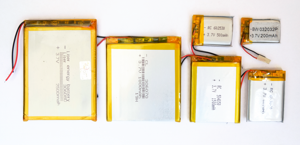
Once we have estimated the energy needs of our project we can move on to the selection of the battery. Of course the bigger the better. But unfortunately we usually have limitations of budget, space or weight. Thus we will have to select the one that is most suitable for us.
If for example we want our project to run for at least 24 hours without sunlight, we will have to make sure that the battery has enough capacity to keep our device running during this time. For example let’s assume (for simplicity) that our project is built with an Arduino Nano, which in total, together with all the other components needs about 100 mAh. In this case in order to have power for a whole day we will need a battery of at least 2400 mAh capacity.

We also have to take into account that batteries degrade with the passage of time, the number of charge cycles performed or that losses that occur in the transformation of the battery voltage. Therefore, it is always advisable to have a buffer to ensure that extra energy. Continuing with the example, we can select a 2500 mAh battery. (Coincidentally 😉 it is the one that will be included in the future Bike Pixels Rear).
Solar panel selection
For our Arduino projects we will normally use a solar panel with a voltage of 5 or 6V. Normally the output power of the panel is expressed in watts (W), and is the maximum amount of energy it can produce under ideal conditions of temperature and sunlight (i.e. given a solar irradiation of 1000 W/m², in a standard atmosphere at 25 °C temperature).
The ideal would be to have a panel that is able to charge our battery during a day. Of course, depending on the weather, time of year and the location where we are (unless we live in the tropics) solar radiation varies so the energy that can produce our solar panel. Therefore, to begin with, we must estimate the amount of solar energy that we can obtain in our location.
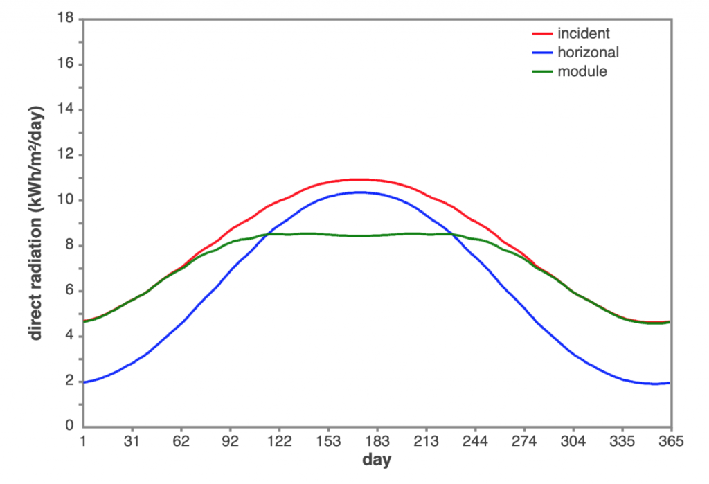
There are many online services that allow us to know the estimated amount of radiation at a given point on the planet. One of them is The POWER Project carried out by NASA. Here we can obtain historical values of horizontal irradiation at any point on the Earth. For example, in the following graphs we have the daily horizontal irradiation in the case of Chicago (USA) during the year 2020.
We can see that on the best days we have just over 8 kW/m² per day and on the worst even less than 1 kW/m²/day. Therefore, in the worst case, our panel will generate in the whole day the equivalent of the power given in its specification. Knowing that the intensity generated by a panel is given by the formula:
I(A) = P(W) / V(V)
If we have a 5V panel that can generate up to 1W of power it will only generate a total of 200 mA for the whole day (1W/5A = 0.2A = 200 mA). This is not enough.
It should be noted that the above graphs present the value on the horizontal, i.e. directly on a flat ground. If we orient our panel perpendicular to the direction of the solar radiation we can obtain extra energy. Continuing with the case of Chicago (latitude ~42°) we can even double the amount of energy in winter if we tilt our panel to around 58° as shown in the following graph obtained thanks to this online tool for calculating solar radiation on an inclined surface.

Thus on the worst days for a 1W panel, we can estimate that we will have 400 mA throughout the day. Thus to charge a 2400 mA battery we will need a panel of at least 6W (2400 mA/400 mA).
Components
To demonstrate the operation of the panel I have prepared a small project with a led. The idea is that it turns on at night and turns off during the day. For simplicity we will pretend that the consumption of this circuit is 100 mAh (although in reality it would be much lower). In this way we can work with the battery and the panel already proposed. For this project, apart from these components and an Arduino board, will be necessary:
- a photoresistor, a led and resistors of 330Ω and 10kΩ, which are the elements that will be used to demonstrate the operation of the set;
- one TP4056 charging module, which will manage the charging and protection of the battery;
- a step-up module that converts the LiPo battery voltage to the 5V required by the Arduino to operate;
- a SR240 diode, which will ensure that no current flows from the battery to the panel.
The SR240 is a Schottky diode. It was chosen because it has a lower voltage drop than conventional silicon diodes. In the SR240 the voltage drop is also particularly small, around 0.55V. This allows us to protect the solar panel while at the same time not reducing its performance too much. In addition, it can work with currents of up to 2A. This ensures that it will be able to work without problems even if the panel is working at its maximum. On days with better conditions the panel of the 6W example can produce up to 1.2A.
The list of components we will need and their prices* is summarized in the following table:
| Componente | Amazon.com | AliExpress |
|---|---|---|
| Arduino Nano | $12.50 (original) | $4.16 (clone) |
| Solar panel 6W | $15.79 | $12.17 |
| TP4056 USB-C module | $7.99 (5 pcs) | $0.52 |
| LiPo battery 2500 mAh | $10.59 | $10.33 |
| Step-up 5V module | $7.29 (5pcs) | $0.41 |
| SR240 Schottky diode | $6.34 (50 pcs) | $2.45 (100 uds.) |
| Photoresistor | $4.25 (30 pcs) | $0.80 (20 uds.) |
| LED | $6.19 (100 pcs) | $1.05 (100 uds.) |
| 10kΩ resistor | $6.99 (200 pcs) | $0.67 (100 uds.) |
| Resistencia 330Ω | $4.99 (100 pcs) | $0.67 (100 uds.) |
| Cables AWG26 | $16.99 (6×32.8ft (10m)) | $18.42 (6x10m) |
Circuit setup and Code
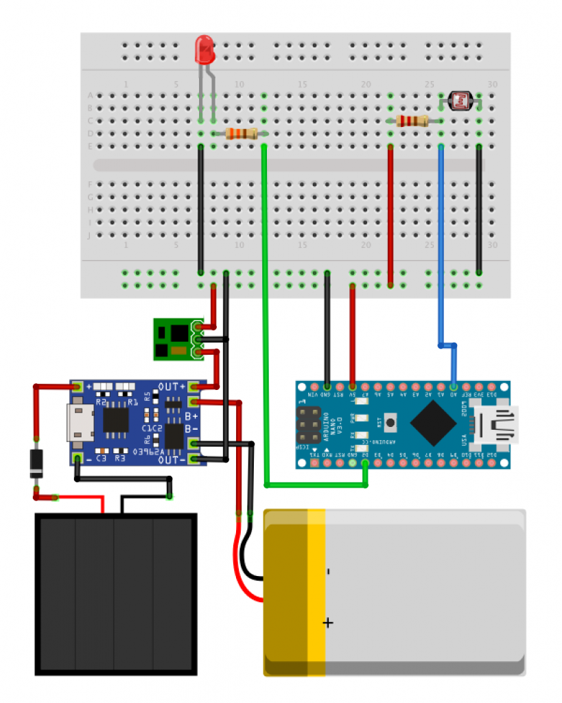
Once the main components have been selected, we can start with the circuit. The configuration will be quite simple. First we must connect the components responsible for powering the Arduino board. The solar panel must be connected to the input pins of the TP4056, the battery to the B+ and B- and the OUT pins to the step-up module. This will be in charge of transforming the current to 5V coming from the battery or directly from the solar panel if it is working. In this way the output of the step-up module can be connected directly to the 5V and GND pins of the Arduino.
Finally we only have to connect the LED to one of the digital pins (for example the 2) and the photoresistor to one of the analog pins (the A0 in this case) as well as to the power supply. In this way our circuit must be as in the configuration given by the following scheme.

Once we have everything ready, we can upload the following code to our board that is responsible for reading the value of the photoresistor and turn on or off the LED depending on its value. With the increase of incident light intensity on the photoresistor, its resistance will decrease so the value read will be higher, that is, the more light the higher the value read by the Arduino and vice versa.
// Pin configuration constants
const int PIN_POTHO = A0;
const int PIN_LED=2;

// Variable storing the value read from the photoresistor (0 to 1023)
int value;

void setup(){
 pinMode(PIN_LED, OUTPUT);
 pinMode(PIN_PHOTO, INPUT);
}

// Photoresistor value reading and set led off if there is light
void loop(){
  value = analogRead(PIN_PHOTO);
  if (value > 50){
    digitalWrite(PIN_LED, LOW);  // Apagar LED
  } else{
    digitalWrite(PIN_LED, HIGH); // Encender LED
  }
  // Wait a second to the next reading
  delay(1000);
}
Conclusion and Further information
The selection of the right components for any project is crucial. In this case we will have to size the battery and the solar panel to fit the energy needs of our Arduino projects and the weather conditions in which we are going to work. We must always study the worst case scenario and base our design on that analysis. We can set the bigger battery and solar panel but this way we will also increase the cost, size and weight of our projects.
If you want to go deeper into the subject of energy consumption and the use of solar energy in your projects, here are some links.
- To learn more about solar energy you can check this complete wiki about photovoltaic energy from scratch.
- In Arduino Project Hub I found a much more complete and complex example using a solar panel to power an IoT project based on Arduino.
- On the same page you have also more than 30 projects related to solar energy for Arduino.
Your suggestions has actually been invaluable when it involves understanding solar energy – thank you for always being a source of understanding and assistance! If there’s something concerning solar energy that interest you, do not be reluctant to connect your input is greater than welcome.