Creating your custom parts for Fritzing
02/09/2020Fritzing is one of the best circuit design and documentation tools. It has a large component base and there are many community-created parts. Even so, sometimes we will not have available some of the ones we want to integrate in our projects. In these cases, creating our own custom parts for Fritzing allows us to add new components based on our own designs.
Right now I’m working on the design of the front version of Bike Pixel. During its design I used several new components such as vertical touch buttons. These are not available in the application and therefore I had to create my own components. Their diagram is shown in the following image:
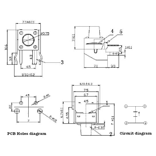
As you can see this is a fairly simple element but it serves very well as an introduction. During developing this example the same steps are performed as in the case of more complicated parts. The only difference is the graphic complexity of the parts and the number of connections.
Creation of graphic elements
The first step to create a new part in Fritzing is to create the images for the four different views in the application:
Breadboard: or protoboard, which will display the component on the virtual test board.
Schematic: which will show the schematic design of the circuit showing its symbols and connections.
PCB: which will represent the connections of the element in a printed circuit.
Icon: which will show the component on the component panel in the application.
- Breadboard: or protoboard, which will display the component on the virtual test board.
- Schematic: which will show the schematic design of the circuit showing its symbols and connections.
- PCB: which will represent the connections of the element in a printed circuit.
- Icon: which will show the component on the component panel in the application.
All these images must be created in SVG vector graphics format. For this I propose to use Inkscape. This is one of the best free applications that allows us to edit and modify vector images. Besides, they have recently released a new beta of the 1.0 version, which I recommend you to download. Of course you can use any other application.
PCB view
We’ll start with the PCB view. For this we will create a new document in Inkscape. The most comfortable way is to work with a grid (for example 0.25mm). To set one up, just go to File/Document Properties and then in the Grid tab create a new one.
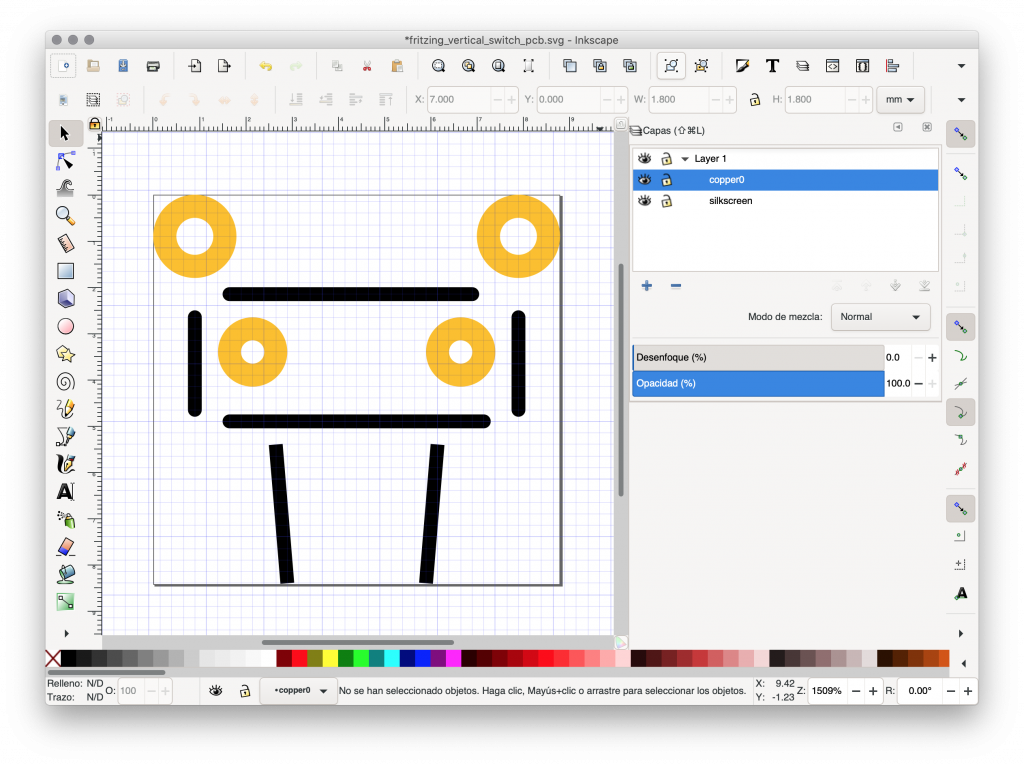
In the next step, it is very important to create the necessary layer structure for Fritzing to import them correctly. We can have any number of layers but it is necessary that your name and ID contain the words silkscreen or copper. In the silkscreen layers only text and borders should be included. On the other hand in the copper layers we include elements like tracks and connectors.
After creating the layer structure we can draw each of the parts of the PCB. If we work with a standard PCB, it is recommended that depending on the element we are trying to add we set:
- Edges and other silkscreened elements with a thickness of about 0.3 mm and solid black (#000000).
- Copper tracks and connectors with a minimum thickness of 0.5 mm using yellow color (#F7BD13 is recommended). In the case of holes it is recommended to use a minimum of 1.0 mm for the drill.
- You should not use texts, but if for some strange reason you want to add them it is recommended to use OCR A font. You can download it from Fritzing’s templates and fonts page.
- We must adjust the measurements to reality, especially in the case of copper elements.
Issues with Inkscape
Finally, as with creating our custom PCB for Fritzing, the hardest part remains. Because Inkscape generates layer IDs automatically, you will need to set them manually from a text editor or the XML editor built into Inkscape. That is, we must open the document with any text editor and look for the layer definition marker (<g>) and change the value of the id attribute to silkscreen or copper depending on what type of layer it is. To make things easier I have created a little script that is available on GitHub and it does exactly the same thing. Just download it and run it by typing:
python3 ink2fritz -i path/file_in.svg -o path/file_out.svgBreadboard view
The view for prototyping is somewhat simpler but also requires some more graphic skills. Before we start working we have to modify the document properties in Inkscape to work in inches (File/Document Properties -> General -> Display Unit).
In general, the element should be drawn with some perspective so that it is possible to see it intuitively once it is placed on the breadboard. In addition, when creating our view we must try to adapt each of the elements to the standard proposed by Fritzing:
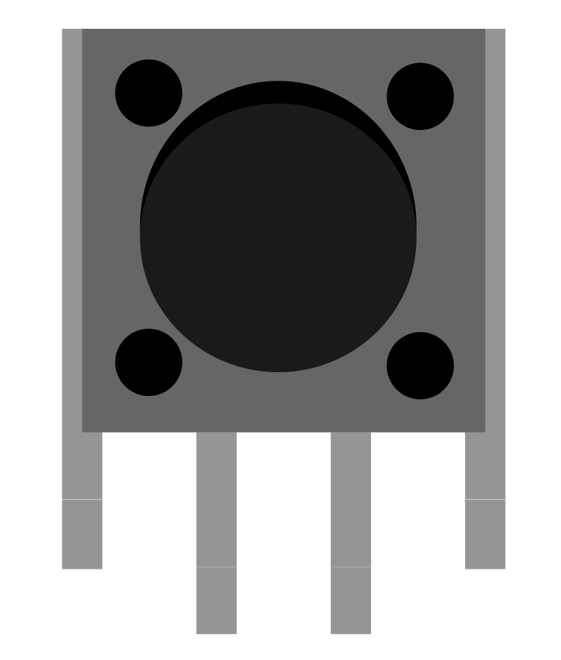
- If the component has legs these must be colored #8C8C8C and spaced at a distance of 0.1 inch and have a thickness of 0.03 inch.
- If the element has copper connections the color #9A916C should be used.
- In the case of text elements we should use the standard OCR A or DroidSans font.
- Of course, you should try to adjust the measurements to reality, especially in the case of legs and connectors.
In our case, as it is a simple element we will have just legs and the rest of graphic elements that represent the part. In this view it won’t be necessary to maintain any convention for the layers either, although it’s always good to keep the order. It is advisable to draw separately the final part of each connector since it will be easier to mark it as a connector element.
Icon view
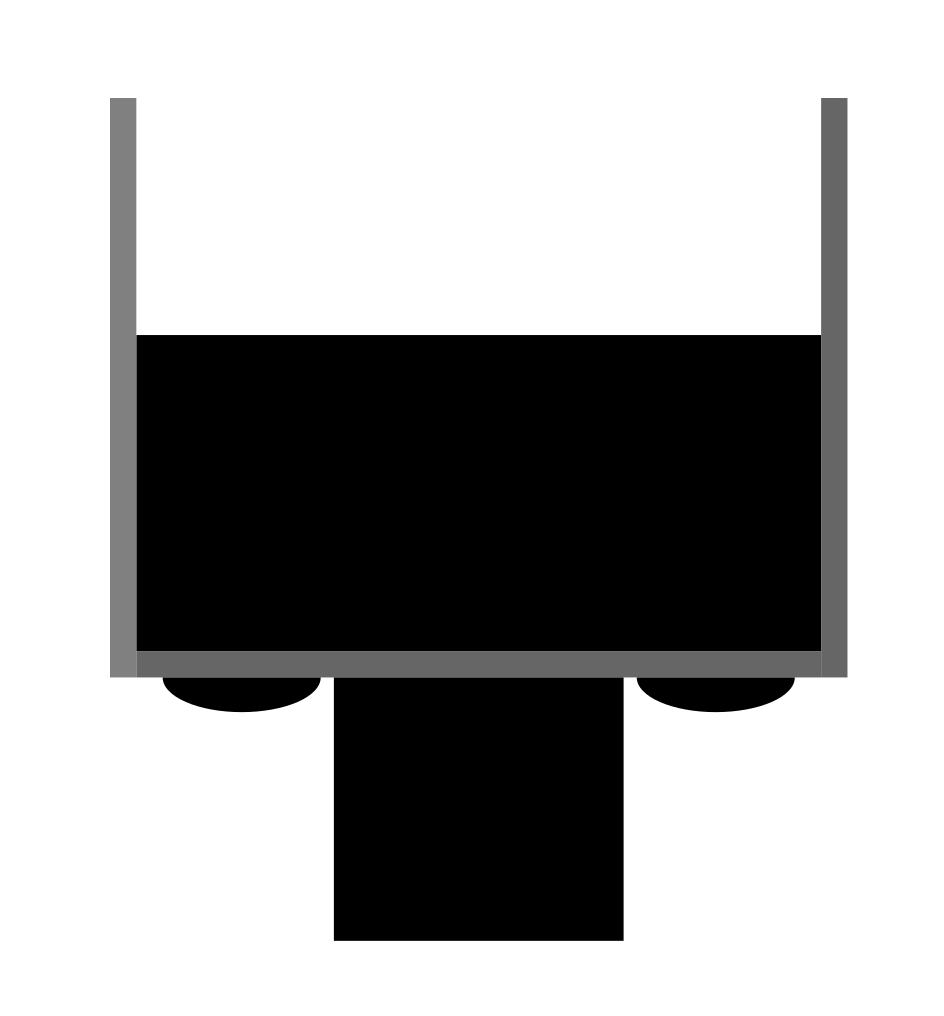
This is the least important view and its function is simply to represent our element in the parts panel.
If you want you can use the same image as the one designed for the Breadboard view although of course we can create a new design. Additionally, in the images we create for this view it is not necessary to consider the real measurements of the piece or to stick to any standard. The only recommendation is not to include text.
Schematic view
In our example, it is not necessary to define this view since it is a simple push button and its schematic is already predefined in Fritzing. But if we want to define a custom schematic view, we need to add the part electronic symbol and mark its connections following a series of conventions for different design elements:
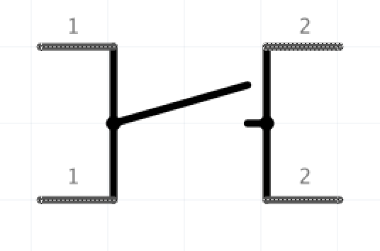
- Colors: black (#000000) should be used for the main body and the name of the part. Dark grey (#555555) for the connector elements and light grey (#999999) for the labels and other texts.
- Texts: Droid Sans typography should be used in different sizes depending on the type of element we are describing. For the component name 4.25 points, 3.5 points for labels and connector descriptions (e.g. GND), and 2.5 points for pin numbering.
- Distances: try to have a length of 0.1 inches for the pins with a line thickness of 0.7 points (or 0.0097′). If you want a detailed example you can download the official templates. In this case I also recommend working with a 0.1′ grid.
Image Naming Convention
Although totally optional, to save the images with our designs it is highly recommended to use a standard for the naming of our files. Fritzing suggests using a file name that includes different file properties including the component name, a brief description, the package name, pin number, spacing, part colour (if there are several options) and the view it will be applied to (breadboard, PCB, etc.). In other words, we should try to adapt the names to the scheme:
part#_desc_package_pins_spac_color_view.svgFor our example I’ve used:
pushbutton_vertical_bikepixels_icon.svgCreation of the custom part
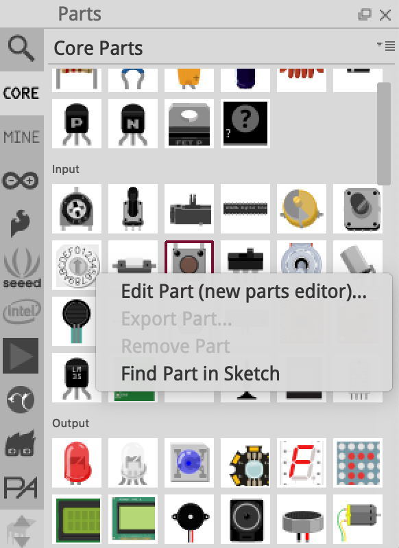
Once we have the images of all the views ready we can start working with the Fritzing part creator. To do this, on the part selection tool, we just have to right click on the most similar component and select the Edit part (new parts editor) option. If, for example, we are creating a new module, we will normally select a DIP-8 integrated circuit in which we will define the connectors that our module has. In this case, as it is a vertical push button I will use the normal push button as a base template.
After selecting the part that will serve as template, the parts editor window will be opened. This tool has six tabs or sections through which we can define each of the four views along with the metadata and connectors of our component.
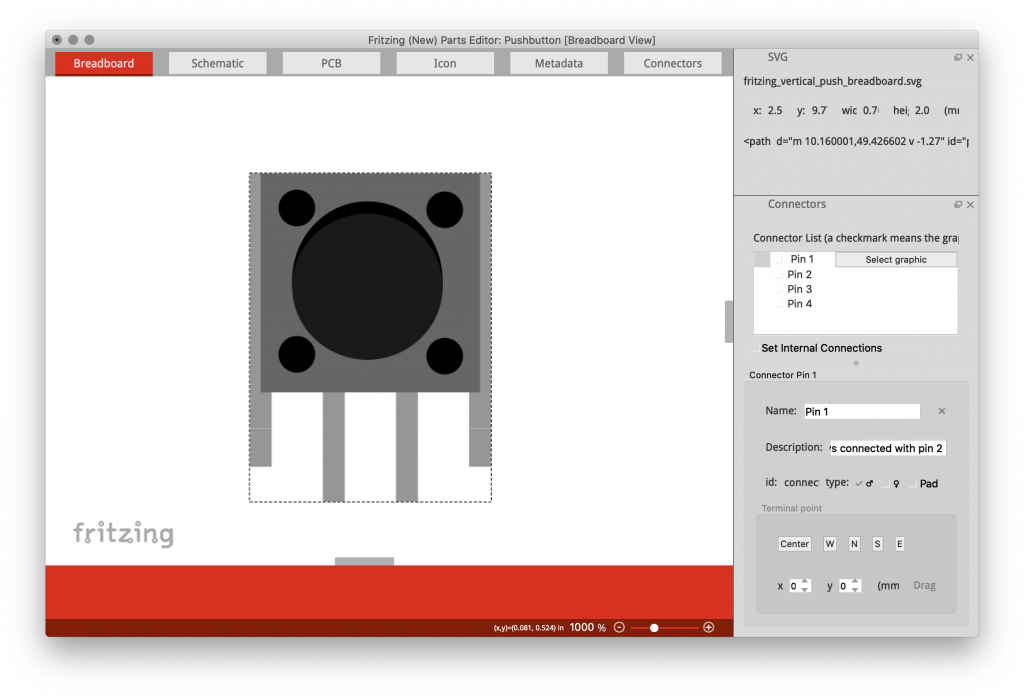
Defining the views
The way to define each of the views is very similar. After selecting the corresponding tab (Breadboard, Schematic, PCB or Icon) we must replace the default image with our design. To do this we just have to select the option File/Load image for view and select the corresponding image path to be used at the view.
Then in each of the views (except the icon view) we will have to configure the connectors. To do this we must assign a geometry from the image to each of the defined connectors. On the side panel, inside the Connectors section we must press the button with the option to Select graphic and click on the geometry we want to assign to that connector (see the video below for clarification).
Metadata and final steps
Finally we only have to define the metadata of our part. To do this in the Metadata tab we must indicate different additional properties of our component as authorship, description, default label and other characteristics.
Once all the data is completed, we can save our part by selecting the option File/Save new part as. In this step we must set a prefix to distinguish our custom parts from other elements, e.g. we can use bikepixels_push_button_vertical.
All these steps can be seen in a more graphically in the following video:
Conclusion and further information
As you have seen, the most laborious part of creating custom components in Fritzing is designing the graphic elements. We must to adapt to the proposed standards and also maintain the real measurements of the part we are creating.
The element designed during this article is part of the design of the future Bike Pixel Front so all the graphic designs as well as the exported component are available in the project repository.
Lastly, for more information below I leave you some useful links:
- Page with the definition of Fritzing’s graphic standards.
- List of links to official documentation on the creation of components.
- Among them a good tutorial created by SparkFun with details on how to create a custom module.
Hi, i looked at your github but could not find any reference to the horizontal button you mention above. Would you considure sharing ?
Hi, sorry it is on the develop branch. You can get it at https://github.com/kstopa/bikepixel/tree/develop/front/electronics/custom%20components.
I’ve already updated the link. Thanks for reading and checking!